Q. Do we have a procedure using OpenRoads Designer to create grade reports and cross section sheets for our construction offices and the eBids package?
A. Yes, WARNING! When saving reports to your C: drive or server locations, it is easiest to deal with the security level permissions if you Save As HTML from the Civil Report Browser. Then open Excel application from your desktop and use the [Open] command to load the HTML file. And finally, use File>Save As (Excel workbook) to save the file as an XLSX. The security level dialog will pop open in Excel so you can select the level.
Now - back to the procedure...First create permanent cross sections for eBids following the instructions in
EBids Cross Sections with Cover Sheet. Then, return to the Default model that contains the named boundaries and run the OpenRoads Modeling>Home>Model Analysis & Reporting>Civil Analysis>Cross Section Report command. Select the Named Boundary Group for the alignment.
Use the revised CrossSectionGradebookfromCL.xsl style sheet in the Custom folder in the Bentley Civil Report Browser.
Q. I'm using Drainage and Utilities in ORD 2023, trying to use "Hydraulic Run From Node" but it doesn't run; what's wrong?
A. There is a known bug in OpenRoads Designer 2023 and "Hydraulic Run From Node" does not function. The workaround is to use "Utility Run From Links" to produce a profile.
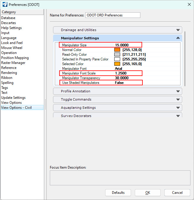
Q. Is there a way to make the civil manipulators more easily visible on high resolution monitors?
A. Edit your preferences by going to File>Settings>User>Preferences...>View Options - Civil and set the Manipulator Settings to the values shown below for larger manipulators and values, and solid-filled icons.
Q. I'm using AutoTURN and it keeps crashing OpenRoads when I select a path; any ideas?
A. Take a close look at the element you are selecting for the path and see if it uses a b-spline element. B-splines have been known to cause software aborts and selecting a b-spline as an AutoTURN path (horizontal or vertical) can certainly cause a crash. A quick workaround is to sketch a linestring over the top of the path that contains the b-spline and use the linestring as your path element.
Q. How can I display the graphics of the mainline corridor in a dynamic profile window of an approach road to help get the approach road to match the main line?
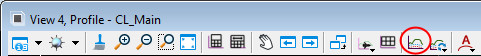
A. Use the Create 3D Cut tool to cut a slice of your 3D model, and display corridors or terrains in the dynamic profile window. This tool can be found in the view control tools of the profile window.
There are two placement methods: Corners and Full Profile. Once the cut is placed in the profile window it can be manipulated by selecting the white dashed boundary of the cut and manipulating the blue handles. The graphics in the cut are static and will not reflect changes to the corridor graphics. Selecting and hovering over the white dashed cut boundary, exposes the fly out menu with three additional tools, Refresh 3d Cut, Refresh 3d Cut With Levels, and Delete. Refresh 3d Cut will redraw the graphics in the cut, but will not reflect any changes to those graphics since the cut was made. Refresh 3d Cut With Levels is the tool needed to refresh the graphics with any changes to level display status. Delete will delete the cut from the profile window. For more information on this tool, check out this 3D Cut Refresh video.
Q. How can I display the proposed profile (vertical alignment) of my roadway in the dynamic Profile Window that shows my drainage network profile run?
A. Use the Project Profile to Element command. The name of this command might seem counter-intuitive, but it projects the vertical alignment (also known as a profile) of a plan element that you select, into the dynamic Profile Window of another plan element. That other plan element might be a different horizontal alignment or a drainage network.
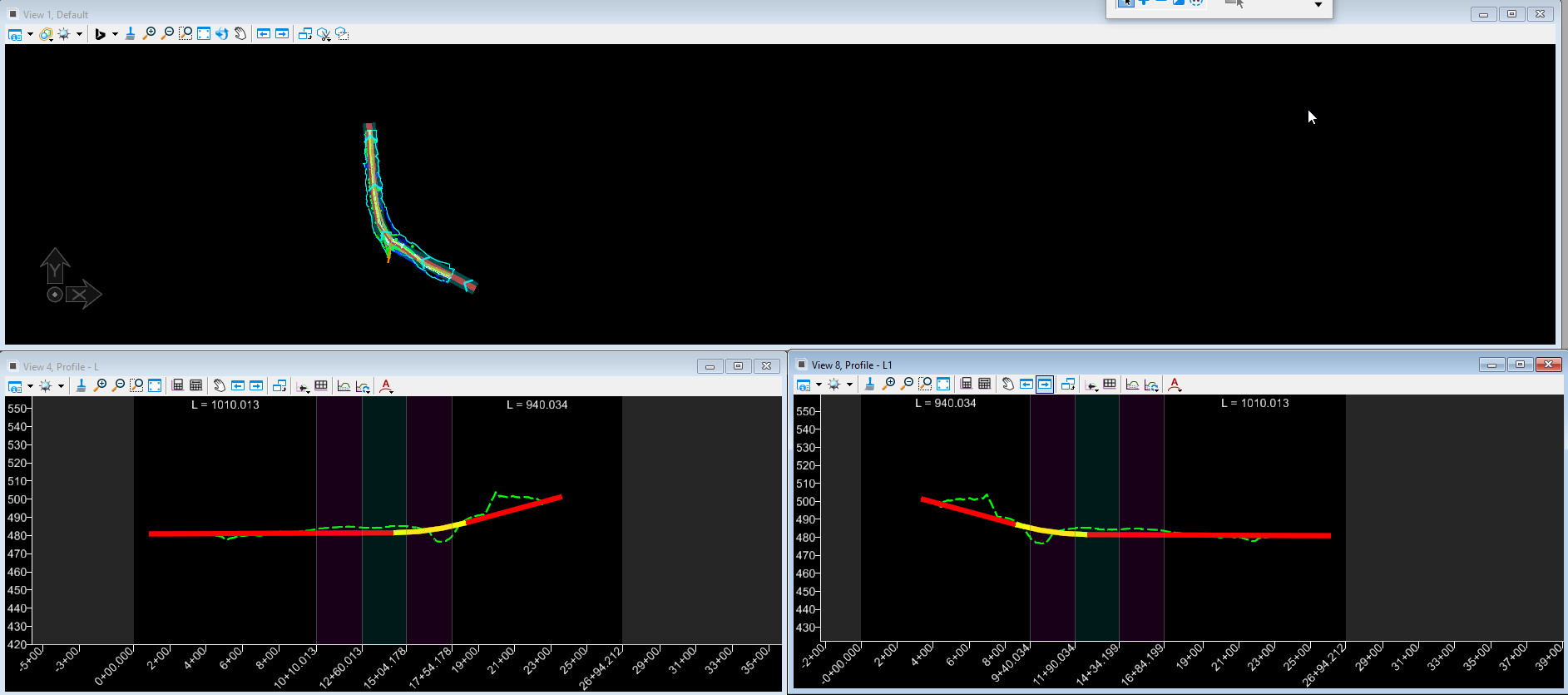
Q. Is there a way to reverse an alignment direction without dropping the complex and re-complexing it?
A. Use Geometry>Horizontal>Modify>Transpose Element. This command makes a copy of the selected geometry and reverses the copy. Transpose Element effectively mirrors both the horizontal and vertical geometries and causes the copy to begin at 0+00. After transposing the element on the complex geometry, use Geometry>Horizontal>Modify>Start Station to apply a start station to the reversed horizontal. The mirrored vertical geometry will maintain its location relative to the horizontal geometry as shown by comparing the profile or the original alignment on the lower left, to the profile of the reversed alignment on the lower right of the picture below.
 Note: Don't use b-splines in horizontal geometry; Bentley warns against it and b-splines have been known to cause software aborts when attempting to transpose or transform geometry.
Q. I have such trouble getting the hover menus for corridors and geometry to appear in OpenRoads Designer; how can I make those open consistently?
A. For best operation of civil commands when using OpenX software, ensure that the tool settings for Element Selection are set to Individual and New (see picture below). That way when you are prompted to "locate" or select an element, you can do so with one left-click. Select the civil element, then move the mouse away and back to hover the tolerance circle over the element. The hover menu will appear after about 2 seconds.
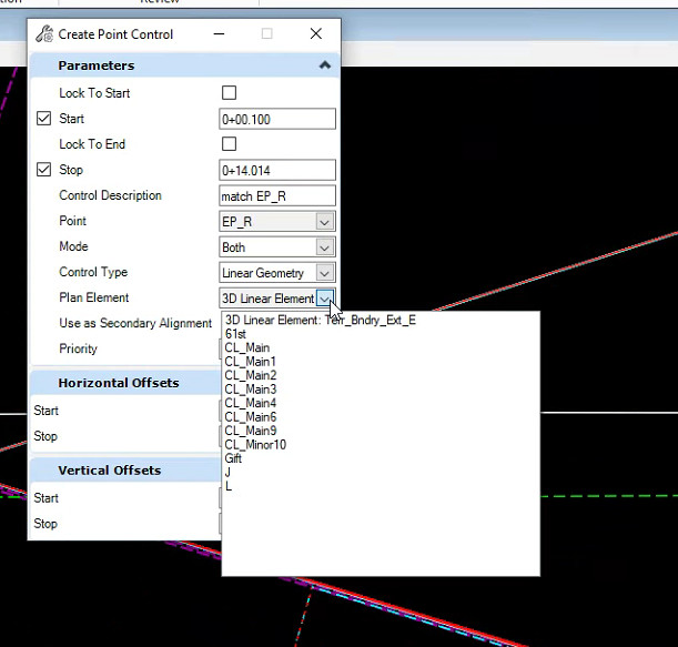
Q. How can I set up a point control to follow a survey feature definition that's in the existing terrain; it doesn't show up in the list of Linear Geometry?
A. You can graphically select referenced Linear Geometry from the Survey existing terrain file, even though they do not appear in the Plan element pull down list. In the Create Point Control dialog,
set the Control Type to Linear Geometry. When prompted to "Locate Plan or Profile Element",
left-click on the graphical element, ignoring the yellow banner pop up that says "Linear Feature - not available". After selecting the graphical element, it will appear in the Plan Element pull down list.

If you wish to use more than one survey linear geometry element as a point control target, consider using Feature Definition and Range. Feature Definition and Range point controls can select linear feature definitions, but not
survey feature definitions that come from a field book. In this case, you could create and reference a FEAT file that holds
3D linear geometry transformed from existing Survey feature definitions.
Q. How can I use OpenRoads Designer or OpenSite Designer to track along an alignment to display station and offset to other points?
A. Use the
Analyze Point command. Analyze Point may be toggled on in your Quick Access Toolbar and may also be found on
OpenRoads (Site) Modeling>Home>Model Analysis & Reporting>Civil Analysis>Analyze Point.
To track along an alignment, make sure that the element you select is a Complex Element or a 3D Linear Element.
Q. Why is my Cross Section Gradebook Report blank?
A. Something is wrong with the data that is feeding the cross section named boundaries. Investigate container files to ensure that they were completely configured and have a Default-3D model; look at corridor graphics and ensure that they can be seen in the 3D view. Check the geometry - if the path element for the cross sections does not have an active profile, that will result in a blank cross section gradebook report. If the geometry graphics don't appear in the 3D view, open the geometry and its profile window, then select "Set As Active Profile".
Q. How do I use OpenRoads Designer to check the names of feature definitions in a proposed terrain?
A. You cannot easily check feature definition names in a proposed terrain. Instead, check them in the corridor. Why? Because template points, when modeled, become feature definitions. Then, the feature definitions are used to create the proposed terrain. The feature definitions take on the name of the template points. The time to perform QC on feature definition names is when they are visible in the corridor, looking at the template point names.
Open the
Corridor Objects for your corridor and from the Template Drops tab select
Edit Template Drop. In the “Editing Roadway Designer Template Drop” dialog, select the “Active Template” tab at the bottom left. In the hierarchy window at the top left, select the Points folder – the point names will all appear in a preview list at the bottom left. This is an easy way to spot leading spaces and misnamed points.
Q. How do I respond to the Alert dialog that says the software must be restarted to load the new configuration and asks, "Do you want to restart now?"
A. Click the [Yes] button.
The Alert dialog will pop up when using MicroStation, OpenSite Designer, and OpenBridge Modeler, as well as when using OpenRoads Designer. The answer is the same for all software - Yes.
Q. How can I see the Bing map aerial image in a sheet assembled using a reference? I'd like to produce a sketch map showing the location image with some graphics drawn on top. The graphics show up in the sheet, but not the aerial.
A. It is recommended that you use the
Raster Manager,
File>Attach>Bing Maps… (at the bottom of the list). Raster references can be clipped and printed when referenced into sheets.
Q. What is a Redundant Reference?
A. Redundant references are recognized by ditto marks (") in the References dialog and by their absence in the reference hierarchy.
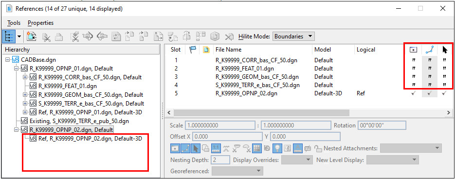
A nested reference with the same location, scale, rotation, and same clip boundary is a duplicate nested reference.
Duplicate nested references whose display is on will not be redrawn and you cannot control the duplicate's reference or level display.
Q. How do I change the template interval when applying a linear template using OpenSite Designer?
A. Use the Stroking Definition group in the properties of the complex element that the linear template is applied to. The Linear Stroking value controls the template interval.
Q. Analyze Elevation produces no report and the command simply closes if terrain is not assigned a feature definition.
A. If a terrain has no Feature Definition assigned, the Analyze Elevation command does not function correctly. Terrains may be created from a field book without a feature definition assigned. The resolution is to Assign a Terrain Feature Definition.
Q. Create Cut/Fill Volumes produces "No Existing Surfaces Found" message; how can I get the meshes created for cross sections?
A. The message means that the terrain you have identified as "Existing" has a boundary that is smaller and within, or coincident to the boundary of the "Design" terrain. One workaround is to swap feature definitions between the two terrains being compared, then create the cut/fill volumes. Another workaround is to edit the boundary of the “Existing” terrain so that it is slightly larger than the “Design” terrain.
Q. What should I do if when opening a DGN file using OpenSite Designer, I get a dialog that says "Incompatible Civil Data"?
A. When you use OpenSite Designer and edit a civil DGN file that was created with OpenRoads Designer, you will be prompted to either open the file as Read-Only or to [Cancel] and close the file.
If you are not the creator/owner of the file and have not been assigned responsibility for the file, by all means, open it Read-Only or attach it as a reference to a file that you own. You should be doing that anyway.
If you are the creator/owner of the file, follow the instructions in "
Align DGN Data for OpenSite Editing" to align the civil schema. After that, you will be able to edit your file with OpenSite Designer.
Q. The File Open dialog for MicroStation or OpenRoads displays a strange document list view from ProjectWise! The columns are not what I expect and I always have to adjust the column widths or sorting to see the names. Can this be fixed?
A. Yes, you can fix the display. When the document list view from ProjectWise doesn't look correct, your ProjectWise "View" needs to be reset. Here's how:
- Exit MicroStation or OpenRoads.
- Open the
ProjectWise Explorer - that's right, it is controlled in ProjectWise!
- Expand the datasource and select the folder that contains the DGN file that you will be opening.
- Ensure that the View toolbar is displayed - if it is not, choose
PW: View>Toolbar>View.
-
Change the View on the View toolbar to a different view - this is the key! Then, set the view back to the view that you prefer.
- Now launch MicroStation or OpenRoads and you should see the document view list in the File Open dialog matches the presently set View in ProjectWise Explorer.
Q. Some of my text and other elements in an OpenRoads DGN won't export to a Google Earth (*.KMZ) file; how do I get all that info into a KMZ/KML file for scoping, RW acquisitions or API report?
A. KMZ files are most correctly exported from a DGN when the graphics are not civil graphics. Take an intermediate step of creating a non-civil graphics file containing just the text and elements that you want to export to a KMZ file.
- Adjust the level display to only what you wish to export.
- Use the Save Fence to File command from Drawing>Home>Selection>Fence Tools
- Follow the prompts to draw a fence around the graphics and create a new file that contains non-civil graphics.
- With the new file open, use File>Export>Visualization File Types>Google Earth (*.kml)
Q. How does the document naming convention and ProjectWise folder usage for OpenRoads Designer DGNs work?
A. All base files that contain civil data (ORD files) will be saved in 6_Civil_Data. 6_Civil_Data is the location of the most up to date and correct information from a designer using ORD. The files are named with
four-character abbreviations like: TERR, GEOM, and CORR. Only the
OPNP file (ORD-generated Plan/Profile Sheets) is stored in the 2_Plan_Sheets folder. The reason for this one exception is because the OPNP file can actually contain plan sheets and for ease of manually attaching references to the design data when manually assembling sheets.
Q. I have referenced the terrain* container file to my corridor file, but when looking at the 3D view or the cross section view, I do not see the existing terrain; what could be the problem? (* it could be a geometry or corridor container file as well)
A. It is likely that the last step in creating the terrain* container file was missed. The owner of the existing terrain may need to simply open the terrain container file using OpenX Designer and use
Set as Active Terrain Model. That will create the OpenX-managed 3D model in the container file so that it can be automatically referenced into your 3D model. (* also true for geometry and corridor container files)
Q. What happens when I make a referenced terrain model active from the Default model in a new 2D file using Set as Active Terrain?
A.
Set as Active Terrain Model is used to cause OpenRoads Designer to do several things automatically, and to set your file up to be used for 3D design. Set as Active Terrain Model is an important last step in the creation of container files.
- Creates an ORD-managed 3D model
- Attaches 3D models in current references to 3D model
- Self-references the 3D model into the 2D model with nesting
- Attaches 3D models in future references to the 3D model
Q. Why do I still see old data displayed in a Container File after I detached it?
A. A better question is "How do I manage reference attachments in a Container File when I am removing an attachment to an older "pub" file?"
Answer is: Don't forget to detach the reference to the older "pub" file from the 3D model. New reference attachments to the 3D model occur automatically when you attach the new "pub" file to the 2D model. But detaching or removing reference attachments must be performed manually in both the 2D and the 3D models.
Q. I cannot tell the existing work from proposed work in a PDF of a plan sheet - the existing graphics are not grayshaded; what could be wrong?
A. Grayshading of existing elements is performed by a
pen table. The pen tables are typically applied using the appropriate
print style. All of that will not work unless the Logical Name of the reference attachment to the data uses a unique name that includes the string "
exist". In the picture below, three reference attachments include the phrase "exist" (highlighted yellow) in their logical names.
In the snip of the resulting PDF shown below, it is obvious that some of the line work is gray-colored and some of the line work is black.
Q. What should I do if when opening a DGN file using OpenRoads Designer, I get a Civil File Upgrade dialog that says "To edit this file it requires upgrading to the installed software version."?
A. Ask yourself, "I am the creator/owner of this file?".
When you use OpenX software and edit a DGN file that was created with ODOT's previous versions of the civil CAD products, you will be prompted to upgrade the civil schema in the file or open the file read-only. If you are the creator of the DGN file - it is recommended that you upgrade the civil schema. If you are prompted to upgrade a file that was created by someone else, courtesy and ProjectWise usage guidelines dictate that you choose to open another's file read-only.
Q. How do I perform ODOT CAD drafting with MicroStation or OpenX Designer?
A. The MicroStation drafting tools are found on the Drawing ribbon workflow in MicroStation and OpenX software. The ODOT standard line styles, cell libraries, text styles and levels are all available when using the OregonDOT WorkSpace. There are even ODOT discipline ribbon workflows that have tabs and commands that are commonly used by each discipline.
Q. Why does the sheet model that I just created not have the correct size (11x17)?
A. Because you did not select
Sheet from Seed, but just used a type named Sheet. The
Sheet from Seed is totally set up as a B size sheet (11x17) and displays the boundary.
Q. What's up with my Feature Definition Toolbar in OpenRoads Designer? There's room on the bottom, why won't it dock there?
A. The Feature Definition toolbar is ever so slightly taller than other toolbars and only docks to the bottom row on monitors with a certain vertical resolution. There is nothing that you can do except float the dialog and don't dock it.
Q. When am I required to use OpenRoads Designer for projects that are in production?
A.
- Projects that have already been created in ProjectWise are likely to continue their life as a “V8i” project if they are at or past DAP by July 1, 2021.
- New projects created in ProjectWise after July 1, 2021 will be assigned the CONNECT Design Platform attribute and managed by ProjectWise. MicroStation V8i and InRoads V8i will not operate in a CONNECT Design Platform project – so MicroStation and OpenX software will be required to be used in these projects.
Q. Does ProjectWise document naming have names for OpenRoads and OpenSite Designer files?
A. Yes. DGN files for straight MicroStation use have not changed and are at the top of the list still when selecting a document description with the ProjectWise Document Naming tool.
Descriptions for OpenX Designer files were added for every discipline at the BOTTOM of the document description list.
Q. Where can I find a list of ProjectWise document names for OpenRoads Designer DGNs?
A. In ProjectWise, in the
_PW_Resources>PW_Standards folder, at the top of the PW_ODOT_PROD datasource, is a spreadsheet named "ProjectWise_Document_Naming_Tool_Search.xslx". Follow the instructions in the active worksheet to display the descriptions, names and correct folders for the discipline that you select.